
 English
 русский
 Português
 Français


 Read More

Product Category
NEW Category
Contact us
Contact Us
We specialise in the research, development and manufacture of electrical wires and cables.
 +86-21-57560276
Biopharma Process Heat Transfer Units: Key Material and Hygienic Requirements
Content
A single heat-transfer leak can destroy an entire biopharmaceutical batch and trigger a costly deviation investigation. In upstream cell culture and downstream purification, the heat transfer unit is the physical boundary between the product stream and the utility media, and its material and hygienic design decide whether that boundary holds. The default specification is 316L stainless steel with an electropolished wetted surface at Ra 0.4 µm max, but the complete requirement extends well beyond those two numbers.
Material Selection Sets the Contamination Boundary
316L stainless steel (UNS S31603) is the standard wetted material for biopharma process heat transfer units because it keeps its corrosion resistance through repeated CIP and SIP cycles. Its low carbon content (0.03% max) prevents chromium carbide precipitation at heat-affected zones during welding, and its 2 to 3% molybdenum resists chloride pitting from caustic, nitric acid, and peracetic acid cleaning agents.
Core definition
Material compliance in a biopharma heat transfer unit means the wetted material preserves its corrosion resistance, surface integrity, and low ionic release across repeated exposure to CIP detergents, hot WFI, and pure steam at 121°C.
Acceptance is verified against material certificates, not assumed from a grade name:
- Carbon content max 0.03% for weld stability and immunity to sensitization.
- Molybdenum content between 2.0 and 3.0% for pitting and crevice resistance.
- Nickel content between 10 and 14% for a stable passive oxide film.
- Controlled ferrite in autogenous welds to prevent preferential corrosion.
- Mill certificates traceable to heat number and production lot for GMP documentation.
The alloy alone does not make a heat exchanger sanitary. A 316L tube with a rough mill finish behaves differently at the microscopic level: rough peaks hold protein residues that survive a standard CIP sequence.
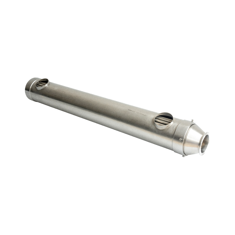
For compact low-flow duties in WFI loops and intermediate hold tanks, a capillary geometry keeps hold-up volume low while maintaining turbulent velocity. Shiloc (Shanghai) Industrial Trading Co., Ltd. supplies the sanitary capillary heat exchanger with fully drainable 316L coil tubes and an electropolished bore.
Surface Finish Requirements
Electropolishing of every wetted surface to Ra 0.4 µm max is the practical requirement for product-contact heat transfer surfaces in biopharma systems. Mechanical polishing to the same arithmetic value is not equivalent: it smears the metal surface, leaving folded peaks that can hide soil and microorganisms.
0.4 µm
Ra max on wetted surfaces per ASME BPE
0.25 µm
Ra spec for WFI loops and chromatography skids
1.5 to 2 m/s
CIP velocity needed for mechanical soil removal
121°C
Standard SIP temperature for heat transfer units
Electropolishing removes the deformed surface layer, lowers the peak-to-valley structure, and enriches the chromium content of the passive oxide film. The result is a surface that is both easier to clean and more corrosion resistant.
Specifying "Ra 0.4 µm max" is meaningful only when it is verified on the finished unit, inside the tube, not at an easy-to-reach header. The purchase specification should name the profilometry method, the measurement locations, and the acceptance value for factory acceptance testing.
Hygienic Design Requirements
A heat transfer unit is hygienic only when it is fully drainable, free of dead legs, crevice-free on every wetted weld, and inspectable from the product side. These properties determine whether the unit can be cleaned and sanitized in place without disassembly.
- Dead-leg ratio: branches and sensor pockets kept to an L/D ratio of max 2 to 3 per ASME BPE.
- Full drainability: shell and tubes slope toward low-point drain connections; no water pockets survive a dry cycle.
- Crevice-free welds: full-penetration orbital welds on tube-to-tubesheet joints, with no exposed threads in product contact.
- Gasket selection: EPDM for hot water, PTFE for aggressive acid steps, perfluoroelastomer for pure steam service.
- Surface access: end caps and tri-clamp ferrules sized so that every wetted surface can be inspected and swabbed.
Leak containment is a hygienic requirement, not a luxury. In a single-tubesheet design, a failed tube joint lets the utility fluid enter the product stream before any sensor can react. A double-tube-sheet design adds a vented interspace between the two tube sheets so that a leak is visible externally before it reaches the product.
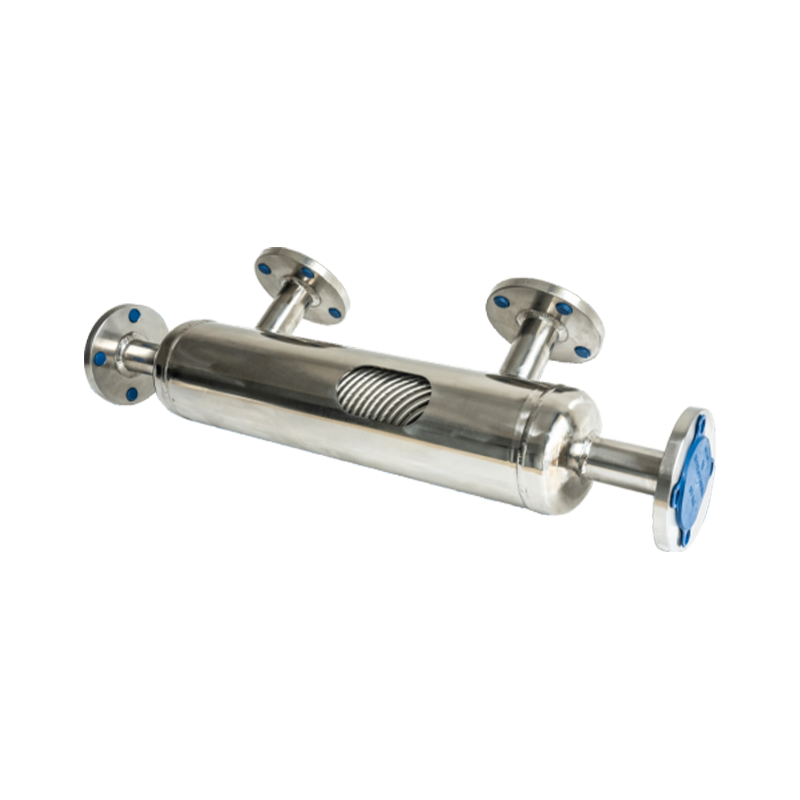
For utilities such as chilled water, glycol, and steam where isolation integrity matters, Shiloc supplies the sanitary DTS double-tube-sheet heat exchanger with a drainable interspace and full material traceability.
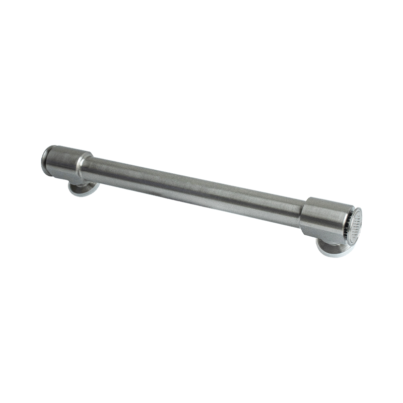 Shiloc Sanitary Double Tube Sheet Heat Exchanger for High-Purity ProcessesThis U-tube design with dual-tube-sheet safety and full-drain capability suits pharmaceutical water systems. Its leak detection points and compliance with FDA and CGMP standards make it a reliable choice where isolation integrity and traceability matter.View Product →
Heat Transfer Geometry Comparison
Capillary, tube-in-tube, and double-tube-sheet units differ in hold-up volume, pressure drop, cleanability, and mechanical robustness. The right choice follows the process duty, not a preference for a single geometry.
| Unit type | Typical duty | Hold-up volume | Cleanability | Best fit |
| Capillary | WFI and hot fluid cooling, small flow rates, fast response | Very low | Excellent | Low-flow loops with temperature-sensitive product |
| DTS double tube sheet | Utility isolation for steam, hot water, and thermal fluids | Medium | Good | Processes where a utility leak into product is unacceptable |
| Tube in tube | High-flow cooling and heating of parenteral and bulk solutions | Low | Excellent | Long runs, high viscosity, and high pressure drop tolerance |
| Pure steam condenser | Aseptic sampling of pure steam and WFI | Very low | Excellent | Steam quality testing and microbial sampling points |
In a WFI distribution loop, a low-hold-up capillary or tube-in-tube unit at 1.5 m/s keeps residence time short and prevents the warm surface from becoming a biofilm promoter. A poorly sized shell-and-tube unit in the same loop can turn into a residence-time incubator at the end of each use cycle.
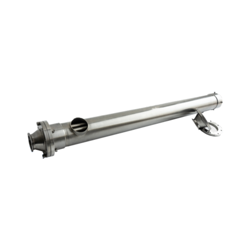
For high-flow product cooling with minimum product hold-up, Shiloc offers the sanitary tube-in-tube heat exchanger in a drainable, single-pass configuration.
 Shiloc Sanitary Tube-in-Tube Heat Exchanger for Low Hold-Up CoolingA drainable single-pass option with concentric tubes handles fibrous or particle-laden products without clogging. Electropolished 316L surfaces and CIP/SIP compatibility support gentle cooling or pasteurization in biopharma and food lines, especially when minimizing product hold-up is critical.View Product →
Compare each option against your flow rate, pressure budget, CIP velocity, and validation strategy before narrowing the selection. Full specification sheets for every verified geometry are collected in our biopharma process heat transfer unit collection.
Integration, Documentation, and Qualification
Hygienic materials and geometry protect the batch only if the unit is integrated, documented, and qualified as part of the process system. The physical exchanger is half the story; the paper trail is the other half.
Factory acceptance testing should verify key hygienic parameters while the unit is still accessible: internal surface roughness at agreed locations, shell and tube hydrostatic tests, drainage angle, and dead-leg dimensions. After installation, the qualification sequence follows the standard GMP route: installation qualification confirms the installed unit matches the approved drawing; operational qualification proves CIP/SIP capability; performance qualification demonstrates that the product temperature is held within the process limit.
Modern biopharma process heat transfer is increasingly delivered as pre-assembled skids with integrated controls, which reduces installation risk and shortens validation time. Shiloc covers this delivery model in more detail in the article on bioprocess integrated skids for modern bioprocess manufacturing, and can support complete turnkey temperature loops for both single-use and stainless process trains.
Frequently Asked Questions
What is the difference between a sanitary heat transfer unit and a standard industrial unit?
A sanitary unit follows hygienic design principles: no dead legs with L/D below 3, full drainability, crevice-free welds, Ra 0.4 µm max electropolished wetted surfaces, and materials that survive CIP with caustic and acid followed by SIP at 121°C.
Why is 316L stainless steel preferred for biopharma heat transfer?
Its low carbon content avoids weld sensitization, its molybdenum content resists chloride pitting, and its passive chromium oxide layer remains stable under repeated sanitization cycles.
What does Ra 0.4 µm mean in practice?
Ra is the arithmetic average of surface height deviations over the measurement length. At 0.4 µm, proteins, microorganisms, and cleaning residues find too few anchoring points to settle, and the surface can be restored by standard CIP.
How is surface finish verified on a finished heat exchanger?
Profilometry per ASME BPE is performed on representative wetted surfaces at agreed locations, typically inside the tube bore and on the product-side header, with results documented in the factory acceptance test report.
The least risky specification combines 316L, electropolished Ra 0.25 to 0.4 µm wetted surfaces, double-tube-sheet isolation for utility services, and a factory acceptance test that verifies every hygienic claim.
PREV:Direct Contact Heat Exchanger: Key Heating and Mixing Requirements in Process
NEXT:Bioprocess Skids for Upstream Processing: Design, Selection, and Benefits
NEXT:Bioprocess Skids for Upstream Processing: Design, Selection, and Benefits
Interested in cooperation or have questions?
Recommended LINS
✦
Process Skid System
Food and Beverage Process System
UHT Processing System for Dairy Products
Food Processing Skid System
UHT Processing Equipment for Plant Based Milk
food and beverage process skid system
Sanitary Process Skid
Skid Mounted Process System
sanitary stainless steel process skid
skid mounted food processing system
Let'S Work Together Welcome Aboard!
-

haikexin@haikexin.com
+8613391278930
-
 +86-21-57560276
-
 No. 2819, Sihu Road,Fengxian District, Shanghai, China
Join Our Mailing List
Copyright © Shiloc (Shanghai) Industrial Trading Co., Ltd. All Rights Reserved.
Process Systems & Equipment For Food & Biopharma Manufacturers
