
 English
 русский
 Português
 Français


 Read More

Product Category
NEW Category
Contact us
Contact Us
We specialise in the research, development and manufacture of electrical wires and cables.
 +86-21-57560276
Tube In Tube Heat Exchanger: Thermal Performance and Process Requirements
Content
- 1 How a Tube-in-Tube Exchanger Is Built and Where It Wins
- 2 Thermal Performance: The Numbers That Decide the Tube Length
- 3 Process Requirements That Override the Thermal Calculation
- 4 Tube-in-Tube, Multi-Tube, Plate or Shell-and-Tube
- 5 Specification and Inspection Checklist
- 6 Practical Questions Engineers Ask Before Ordering
Two suppliers quote the same 4 m3/h dairy cooling duty. One returns a tube-in-tube heat exchanger 6 metres long, the other 9 metres long with a 12 per cent higher price and a 15 per cent lower pressure drop. Neither thermal calculation is wrong. The difference comes from decisions taken before the first heat transfer equation was solved: the fouling allowance, the product velocity and the surface finish written into the process specification.
A tube-in-tube heat exchanger is the most predictable thermal device in sanitary processing. Its geometry can be modelled by hand, its counter-current flow pattern needs no correction factor, and its product channel can be opened, inspected and cleaned without pulling a tube bundle. That is why dairy, beverage and biopharmaceutical plants still order them in 2026, long after plate and shell-and-tube units took over the large duties.
Thermal performance and process requirements pull against each other on this exchanger type. A design that pushes the overall heat transfer coefficient upward usually needs higher velocities and narrower flow channels, and the same choices raise pressure drop, increase product shear damage and make cleaning harder.
Sizing rule of thumb: below 30 m2 of transfer area and 5 m3/h of product flow, a tube-in-tube or multi-tube exchanger is normally the cleanest and least expensive answer.
How a Tube-in-Tube Exchanger Is Built and Where It Wins
A tube-in-tube heat exchanger passes one fluid through an inner tube and the second fluid through the annulus formed by a jacket pipe wrapped around it, in counter-current flow, which gives a logarithmic mean temperature difference correction factor of F = 1.0 across the whole duty.
Because the streams travel in true counter-current directions, a tube-in-tube unit can reach a temperature cross: the cold stream can leave hotter than the hot stream leaves. A single-pass shell-and-tube exchanger cannot do that without two shells in series.
Geometry in practical sizes
- Inner tube DN20 to DN50; a DN25 tube gives about 0.079 m2 of transfer area per metre of length.
- Jacket DN50 to DN100; annulus hydraulic diameter equals jacket inside diameter minus inner tube outside diameter.
- Standard lengths of 1.5 m, 3 m and 6 m, joined in series with U-bends or return headers for longer duties.
- 316L stainless steel (UNS S31603) for product contact; biopharmaceutical units follow ASME BPE-2022.
Where it beats a shell-and-tube unit
- High-solids or fibrous product, because there are no baffles to trap particles.
- Small duties with a tight temperature approach, where F = 1.0 matters.
- Viscous product that needs a narrow annulus to keep wall shear rate high.
- Frequent product changeover, because the tube is inspected and swabbed without a bundle pull.
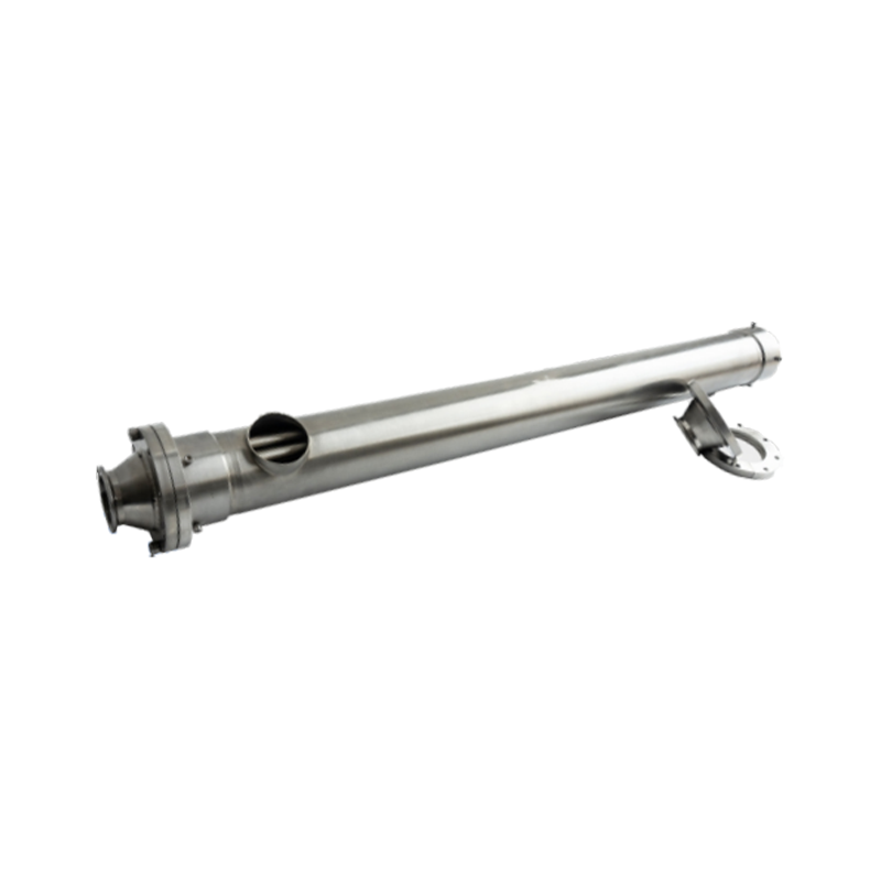
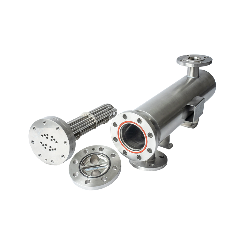
 Tube-in-Tube and Multi-Tube Heat ExchangerModular concentric tube design with food-grade stainless steel, supporting CIP and disassembly cleaning, suitable for hygienic processing and high-viscosity media.View Product →
A tube-in-tube exchanger is not a scaled-down shell-and-tube unit. Removing the baffles removes the cross-flow that lifts shell-side coefficients, so a tube-in-tube design usually needs 20 to 40 per cent more surface area for the same duty. It wins on cleanability, not on raw thermal efficiency.
Thermal Performance: The Numbers That Decide the Tube Length
In clean water-to-water service a tube-in-tube exchanger reaches an overall heat transfer coefficient of 900 to 1,500 W/m2K; the same hardware handling a 5,000 mPa.s product falls to 300 to 700 W/m2K, a threefold difference in required area for an identical duty.
F = 1.0 LMTD correction, true counter-current flow
0.079 m2/m Transfer area per metre, DN25 inner tube
Re above 10,000 Target Reynolds number, product side
| Service | Typical U (W/m2K) | Fouling allowance (m2K/W) | Sizing note |
| Water to water | 900 - 1,500 | 0.00009 | Treated cooling water on both sides |
| Steam to water | 1,500 - 3,000 | 0.00009 | Condensing steam, no subcooling |
| Dairy product to chilled water | 300 - 700 | 0.00018 | Turbulent product flow, cleanable surfaces |
| WFI or buffer cooling | 600 - 1,100 | 0.00009 | ASME BPE finish, small temperature approach |
| Viscous syrup or concentrate | 150 - 350 | 0.00035 | Laminar film, static mixers often required |
Two variables move those figures more than any other: the product-side Reynolds number and the fouling allowance. Below a Reynolds number of roughly 10,000 the product film coefficient collapses, and the exchanger has to grow in length rather than in diameter.
Typical overall heat transfer coefficient by service (W/m2K)
Fouling resistance is added to the clean overall resistance, so the penalty is not linear. Raising the dairy fouling allowance from 0.00009 to 0.00018 m2K/W on a duty whose clean overall resistance is 0.001 m2K/W drops the effective coefficient from 917 to 847 W/m2K, an 8 per cent increase in required surface area.
Process Requirements That Override the Thermal Calculation
Three process requirements decide whether a thermally correct tube-in-tube exchanger passes commissioning: a product-contact surface finish of Ra 0.8 um or finer, a cleaning velocity of at least 1.5 m/s, and a documented hydrostatic test at 1.5 times design pressure.
Hygienic finish and weld quality
Food and beverage units are specified to Ra 0.8 um or finer under 3-A Sanitary Standard 12-06 and EHEDG Doc. 8. Biopharmaceutical units follow ASME BPE-2022, where product contact is normally Ra 0.4 um electropolished, welds are orbital and crevice-free, and every product weld is verified by borescope and dye penetrant. The full set of material and finish expectations is set out in this guide to sanitary heat exchanger surface finish and hygienic requirements.
Cleaning and drainability
Clean-in-place performance is a velocity problem, not a chemistry problem. 3-A Sanitary Standard 12-06 requires a minimum cleaning velocity of 1.5 m/s through the product channel, and high-solids dairy products are normally cleaned at 2.0 m/s. The unit also needs 1 to 2 per cent drain slope, no horizontal dead legs longer than two pipe diameters, and vertical mounting wherever product can settle.
Pressure, temperature and thermal expansion
Sanitary tube-in-tube units are usually designed for 10 bar, with higher-pressure utility jackets taken to 25 bar. ASME VIII Div. 1 UG-99 requires a hydrostatic test at 1.5 times design pressure. Expansion matters just as much: 316L stainless steel grows 16.5 x 10^-6 per deg C, so a 120 deg C swing across a 6 m unit moves each end about 12 mm, and the inner tube and jacket rarely sit at the same temperature.
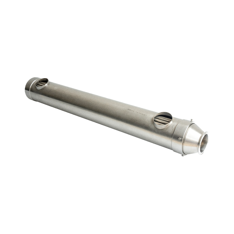
 Sanitary Tube-in-Tube Heat Exchanger UnitConcentric tube design with 316L stainless steel, electropolished to Ra ≤ 0.5 μm, handles fibrous products and supports CIP/SIP, ideal for low-surface-area duties.View Product →
Risk
A unit that meets its thermal duty but carries a 3 mm weld undercut at the inner tube joint will fail a 3-A inspection regardless of its U value.
Tube-in-Tube, Multi-Tube, Plate or Shell-and-Tube
Below 30 m2 of surface area and 5 m3/h of product flow, tube-in-tube and multi-tube units normally win on cleanability and installed cost; above 100 m2, a plate or shell-and-tube exchanger is the only commercially sensible option.
Stay with tube-in-tube or multi-tube when
- Duty is below 30 m2 of transfer area.
- Product carries solids, fibres or pulp.
- A temperature cross is required.
- Batch changeover and inspection are frequent.
- Tube-side fouling must be brushed mechanically.
Move to another type when
- Duty exceeds 100 m2 of transfer area.
- Clean fluids need a 2 deg C approach, where a plate unit reaches U above 3,000 W/m2K.
- Design pressure exceeds 25 bar, which favours shell-and-tube construction.
- Clean steam is the heating medium and plate gaskets are acceptable.
- Floor space, not cleanability, is the binding constraint.
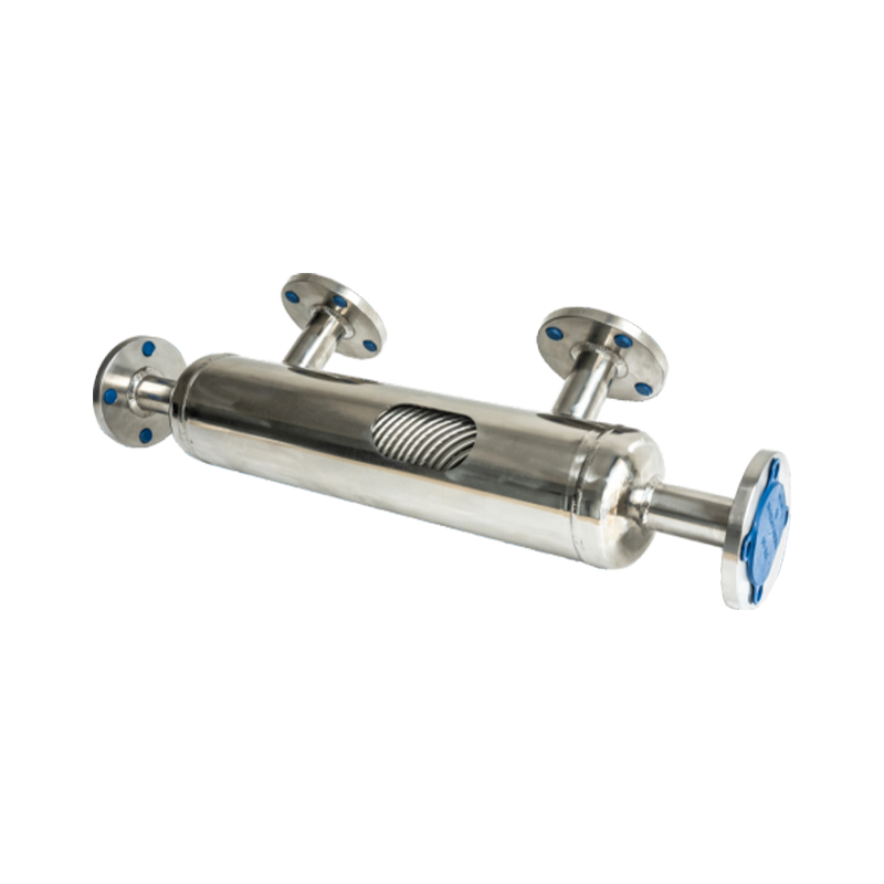
 Flanged Shell and Tube Heat ExchangerStainless-steel shell-and-tube unit with removable flanged end covers for inspection and cleaning, suitable for large-scale heating, cooling, and condensation duties.View Product →
Matching type to duty is a supplier conversation as much as a calculation. Shiloc (Shanghai) Industrial Trading Co., Ltd., trading as Shanghai Haikexin Fluid Equipment, builds sanitary heat transfer units for both the food and beverage and biopharmaceutical industries, and its engineering and export capability is summarised in its company profile.
Installed cost crosses over somewhere between 20 and 40 m2. A bank of six tube-in-tube units needs six flange sets, six gasket pairs and six support points, and the extra leak paths usually make a plate or shell-and-tube unit cheaper beyond that point.
Specification and Inspection Checklist
A tube-in-tube exchanger datasheet should close seven items before the purchase order is released; leaving any one of them open is the most common reason a factory acceptance test has to be repeated.
Duty and terminal temperatures, with the fouling allowance stated as a separate number rather than folded into the U value.
Flow regime: product velocity 1.5 to 2.5 m/s and Reynolds number above 10,000 at minimum flow, not at design flow.
Surface finish and weld inspection: Ra 0.8 um, borescope on every product weld, dye penetrant per ASME Section V Article 6.
Design pressure and test: 10 bar design, hydrostatic test at 1.5 times design pressure per ASME VIII Div. 1 UG-99, plus helium leak testing for biopharmaceutical duty.
Drainability: 1 to 2 per cent slope, horizontal dead legs shorter than two pipe diameters, CIP supply sized for 1.5 m/s or higher.
Thermal expansion case: hottest and coldest operating combination, with differential movement between inner tube and jacket calculated.
Material traceability: 316L (UNS S31603) with EN 10204 3.1 certificates, a roughness measurement report and a passivation record.
Fouling allowance is the most expensive single line on the datasheet. On a 12 m2 dairy duty, an extra 0.0001 m2K/W of allowance can add roughly 1 m2 of surface, about 8 per cent of the purchase price, for a condition that may never occur in normal operation.
Practical Questions Engineers Ask Before Ordering
What surface area can a single tube-in-tube exchanger cover?
A single DN25 unit 6 m long provides about 0.47 m2 of transfer area. Multi-tube shells carrying 7 to 19 inner tubes reach 3 to 9 m2 per shell, and series banks extend the practical range to roughly 30 m2.
Can a tube-in-tube exchanger achieve a temperature cross?
Yes. With F = 1.0, a product can be heated from 20 to 72 deg C by water entering at 70 deg C. A single shell-and-tube pass cannot deliver that and would need two shells in series.
How large should the fouling allowance be?
Follow TEMA for the service: 0.00009 m2K/W for treated cooling water, 0.00018 m2K/W for dairy product and 0.00035 m2K/W for syrup. Every 0.0001 m2K/W added to a duty with a clean resistance of 0.001 m2K/W costs about 9 per cent more surface area.
Which surface finish is required for biopharmaceutical units?
ASME BPE-2022 governs. Product contact and water-for-injection service are normally specified at Ra 0.4 um electropolished, while food and beverage duty under 3-A Sanitary Standard 12-06 accepts Ra 0.8 um mechanically polished.
The thermal calculation tells you the tube length. The process specification tells you whether the unit can be cleaned, inspected and released.
PREV:No previous article
NEXT:Direct Contact Heat Exchanger: Key Heating and Mixing Requirements in Process
NEXT:Direct Contact Heat Exchanger: Key Heating and Mixing Requirements in Process
Interested in cooperation or have questions?
Recommended LINS
✦
Process Skid System
Food and Beverage Process System
UHT Processing System for Dairy Products
Food Processing Skid System
food and beverage process skid system
UHT Processing Equipment for Plant Based Milk
CIP Skid System for Food Industry
Sanitary Process Skid
Skid Mounted Process System
food ingredient mixing skid system
Let'S Work Together Welcome Aboard!
-

haikexin@haikexin.com
+8613391278930
-
 +86-21-57560276
-
 No. 2819, Sihu Road,Fengxian District, Shanghai, China
Join Our Mailing List
Copyright © Shiloc (Shanghai) Industrial Trading Co., Ltd. All Rights Reserved.
Process Systems & Equipment For Food & Biopharma Manufacturers
